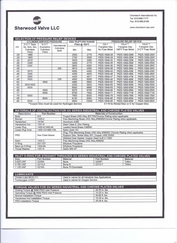
Chlorine Gas Valves
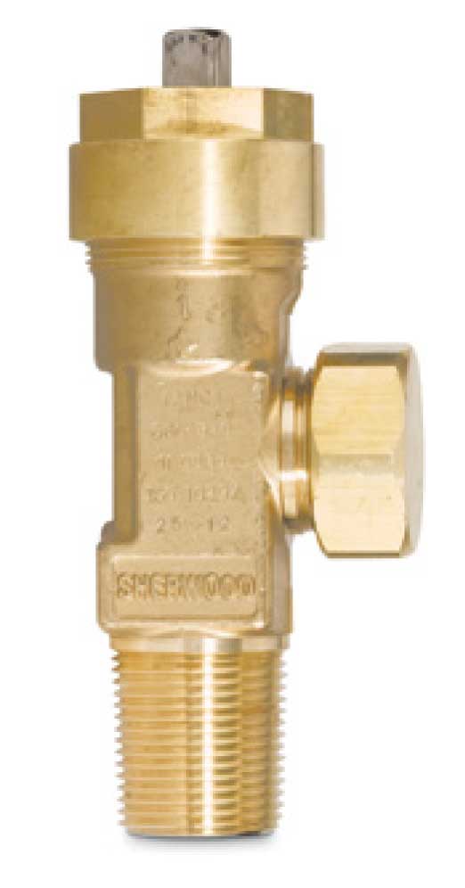
Robust Valve
The Sherwood Exclusive Robust Valve features a heavy-duty body and packing nut for increased load carrying capacity and resistance against stress corrosion and cracking.
Key Features & Benefits
- Approved per the Chlorine Institute Pamphlet 17 Alternate Design Criteria
- Design retains same outlet, inlets, pressure relief device, packing ring, packings, follower, outlet cap, wrenches, yoke and materials as the basic valve
- One-piece Monel® stem offers exceptional durability and positive shut-off in chlorine and other corrosive gas service
- Choice of PTFE (shown here) or Garlock® 6130 packing for easy operation and durable leak-resistant stem seal
- Large wrench flats on valve body for easy installation
- Robust Aluminum Silicon Bronze (C64210) valve body offers corrosion resistance


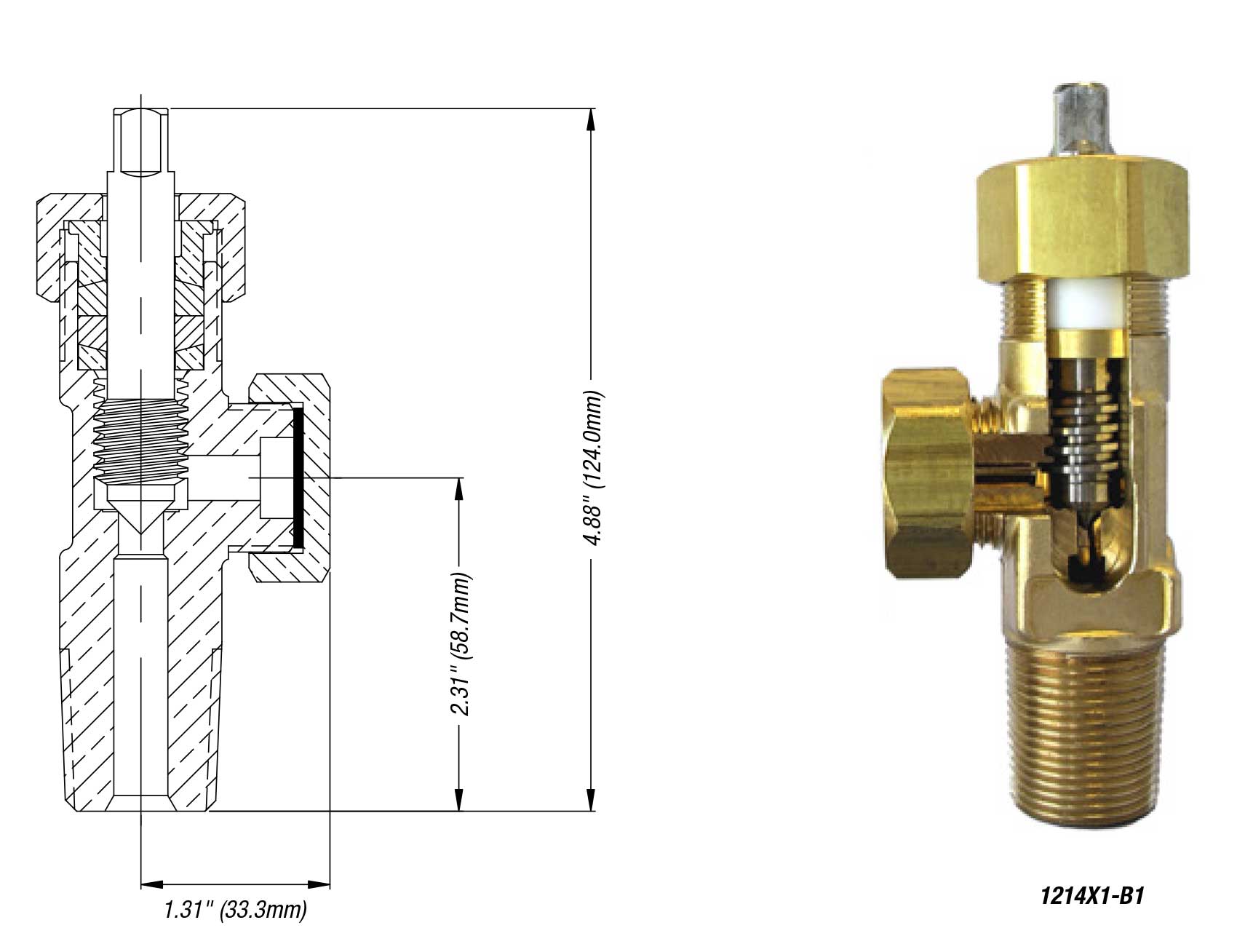
Basic Valve
Key Features & Benefits
- Manufactured in conformance to Chlorine Institute Pamphlet 17
- One-piece Monel® stem offers exceptional durability and positive shut-off in chlorine and other corrosive gas service
- Choice of PTFE (shown here) or Garlock® 6130 packing for easy operation and durable leak-resistant stem seal
- Large wrench flats on valve body for easy installation
- Robust Aluminum Silicon Bronze (C64210) valve body offers corrosion resistance
Chlorine Gas Valves Parts and Accessories

Yoke

Fusible plugs
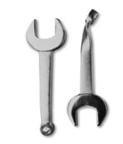
Wrenches
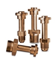
High flow yoke adapters

Flex connectors
Repair Instructions for All Chlorine Gas Valves
WARNING:
In order to ensure proper and continued performance of Sherwood products, regular inspection and maintenance are required to detect any corrosion or unusual wear of metallic and non-metallic parts.
These instructions are intended for trained chlorine valve installers and repairers. If you are not familiar with chlorine valve equipment and applications, do not proceed.
Disassembly of Valve
A. Place the valve assembly into a vise or similar holding fixture. The holding fixture must securely grip the valve body on the wrench flats so no damage is done to the internal bores, external or internal
threads, outlet or fusible plug PRD.
B. Chamber
1. Using a 11⁄4″ socket or hex box wrench, remove the packing nut by turning it counter-clockwise.
2. Using a 3⁄8″ square socket or open end wrench, remove the stem from the valve chamber by turning it counter-clockwise. The packing gland, the two packings and the packing collar will be removed with the stem.
3. Remove the packing gland, the two packings and the packing collar from the stem.
C. Outlet
1. Remove the outlet cap from the valve assembly by turning it counter-clockwise.
D. Fusible Plug Pressure Relief Device (Cylinder Valves)
1. Using a 7⁄16″ socket or hex box wrench, remove the fusible plug PRD by turning it counter-clockwise.
Inspection of Valve and Components
A. Valve Body
1. Inspect the valve body for cracks. If cracks are suspected, scrap the valve body. Inspect the valve body chamber bore for dirt, debris and damage. Blow out the valve body chamber using clean, dry compressed air or nitrogen to remove these contaminants.
2. Examine all internal and external threads for damage or deterioration due to wear or corrosion. Special attention should be given to the threads closest to the outlet since they are the most vulnerable to corrosive attack.
3. Examine the valve body seat for excessive wear or corrosion build up. Wear creating a 1⁄8″ x 90˚ or greater bevel should be eliminated with the 1534 refacing tool (1210/1214) or 1534A refacing tool (1210A/1214A). The valve has reached its end of life and should be replaced when the tool can no longer remove this bevel.
4. Clean the internal threads for the fusible plug to remove all thread luting compound.
5. If the valve body is damaged or corroded, do not attempt to repair. Order a new valve assembly.
B. Components
1. Scrap any component that is suspected of being cracked. Also, replace components damaged, worn or corroded to the point where safe operation, valve performance or leak integrity may be compromised. Special attention should be given to wear grooves in the nose of the stem. Stems with grooves 1⁄64″ or greater in depth should be replaced.
2. Special attention should be given to the fuse plug for signs of leakage. An extrusion of the fusible metal greater than 1⁄64″ may adversely affect use of the emergency kit tool used to temporarily seal fusible metal leaks.
3. It is recommended that both of the packings be replaced before the valve is reassembled.
Assembly of Valve
NOTE: All parts must be clean, free of oil, chips and other contaminants before beginning assembly. A properly calibrated torque wrench must be used. Overtightening will damage components and the valve body. Undertightening may result in leaks. Reassembly of a used valve should not begin until all the components of that valve have been examined to determine their combined effects on valve performance and operation.
A. Chamber
1. Insert the stem into the valve chamber and turn it clockwise; engage it one full thread. Engaging the stem more than one full thread may make installation of parts difficult.
2. Place the packing collar, flat side down, onto the stem.
3. Install two packings with the flat sides facing each other, and place them onto the stem.
4. Place the packing gland with the beveled end down onto the stem.
5. Tighten the stem using a 3⁄8″ square socket and a torque wrench to 10–12 ft.-lbs. to coin the seat in the body.
6. Press down on the packing gland until the two packings are completely below the top of the body.
7. Install the packing nut over the stem. Making sure the threads are properly engaged, tighten the packing nut to 25–30 ft.-lbs. using a 11⁄4″ socket and torque wrench.
B. Outlet
1. Install the outlet cap onto the valve assembly outlet, turning clockwise until hand tight.
C. Fusible Plug PRD (Cylinder Valve)
1. Apply a chlorine-compatible thread luting compound onto the bottom threads of the fusible plug PRD.
2. Thread the fusible plug PRD, finger tight, making sure at least one thread is engaged in the body.
3. Using a 7⁄16″ socket and a proper torque wrench, tighten the fusible plug to 12–15 ft.-lbs. or 11⁄2–2 turns.
Testing of Assembled Valve
NOTE: Only leak detection solutions compatible with chlorine should be used. Thus, only commercial or household detergents should be used that DO NOT contain ammonia, phosphates or other chemicals which are harmful to copper alloys and can initiate stress corrosion cracking of these alloys.
A. Test each reassembled valve by installing the valve securely in a suitable test fixture and pressurizing the valve with air, nitrogen or carbon dioxide to 500 psig.
B. With the outlet plugged or capped, open the valve assembly slowly and check for leaks through the valve body, past the stem and all threaded connections using a leak detection solution.
C. Close the valve assembly and remove the outlet cap assembly or plug. Pressurize the valve to 500 psig and check for seat leakage through the outlet.
D. If any leakage is detected, in the open or closed position, make necessary repairs and retest the valve before returning to service.
NOTE: Periodic retightening of the packing nut to 25-30 ft.-lbs. may be required to maintain a leak-tight packing nut and stem seal. However, tightening more than is necessary or applying excessive torques will prematurely wear the packings and may damage the packing nut and the valve body threads.
Get a Custom Quote
Fill out the form below.

