Compressed Gas Valves

Compressed Gas Valves
Designed for use in every country around the world, our Global Industrial Gas Valve, the GSV Series is designed to meet the newest revision of ISO 10297 and CGA V-9. For use in cylinders containing inerts, oxidizers and flammables.
Key Features & Benefits
- Automated assembly and testing processes ensure exceptional quality
- 100% helium leak tested
- Heavy-duty forged brass body for durability and high pressure
- Precisely machined internal components meet the most stringent international valve
performance standards - Pressure Relief Device (PRD) is a unitized plug design that provides excellent flow
characteristics, ensures proper assembly and tamper resistance - Improved metal-to-metal seal below bonnet threads prevents pressure in the
threads at top of valve body - Direct-drive stem design with optimized O-ring (GSV) or double O-ring (GSHV)
seal reduces friction and operates at exceptionally low torque levels - Inlet and outlet thread configurations are available for a broad spectrum of customer,
country and code specifications - Inlets tapped (1⁄4″ NPT) for dip tube as required
GSV Series Cylinders For Manifold, Oxygen and Fuel Gas

Large Cylinder Acetylene Valves

Key Features & Benefits
- Durable forged brass body, precisely machined internal components and design elements have been upgraded to meet the newest revision of ISO 10297 and CGA V-9.
- High-temperature aluminum alloy handwheel with large drainage holes
- 100% helium leak tested
- Designed with low-torque operation for easy hand use
- Durable lower plug made of tough naval brass resists wear
- Precise quality machining results in exceptional finishes for low-torque sealing
- Metal-to-metal seal below bonnet threads prevents pressure accumulation at top of valve body
- High durometer back-up ring prevents extrusion of O-ring in extreme applications
- Peroxide curing of elastomeric seals enhances valve longevity
- Direct drive stem design with optimized single O-ring seal reduces friction and operates at exceptionally low torque levels
GSVT Series Vertical Outlet Acetylene Valves

Key Features & Benefits
- This valve is used on 360° collar type cylinders (including WB, WQ, WS, WT and WK style)
- Heavy-duty brass forged body
- O-ring designed for leak integrity and easy operation
- Handwheel eliminates interference with cylinder collar
- Easy-to-read valve markings roll stamped on outlet neck
- Soft seat design provides positive shut-off
GSRPV Series Residual Pressure Valves

Residual pressure valve designed to protect cylinder and contents.
Key Features & Benefits
- Prevents backflow of impurities and foreign substances
- Automated assembly and testing processes ensure exceptional quality
- 100% helium leak tested
- Durable forged brass body, precisely machined internal components and design elements meet the most stringent international valve performance standards
- Innovative design and quality construction offer protection of cylinder contents without the expense of a time-consuming purgeand-clean cycle
- Retains approximately 30 to 50 PSI pressure, maintaining the integrity of the cylinder contents against contaminants, even if the valve is left open
- Protects and extends life of cylinder by preventing ingress of moisture
- Pressure Relief Device (PRD) is a unitized plug design that provides excellent flow characteristics, ensures proper assembly and tamper resistance
- Dynamic front piston seal design is not in direct contact with the flow passage during filling
- Inlet and outlet thread configurations are available for a broad spectrum of customer, country and code specifications
- Optical Character Recognition technology utilized to verify appropriate burst disc pressure rating
- Exclusive “webbed washer” design protects burst disc during handling and bulk shipment
- Inlets tapped (1⁄4″ NPT) for dip tube as required
Fill Adapters for GSRPV Series
Retractable Pin Adapters provide maximum operating flexibility to fill or evacuate a cylinder with either a conventional valve or a GSRPV. Engage the Pin Locking Tool (see below) and rotate the tool clockwise to depress the pin for use with a conventional valve. Or rotate the tool counterclockwise to release the pin for use with a GSRPV valve. The adapters incorporate an O-ring seal for a hand-tight connection.
Gas cylinders can be checked for content integrity by simply inserting the Checking Rod and pushing against the resistance of the check valve. The sound of escaping gas indicates residual cylinder pressure.
*Adapters can be used with TV RPV and GRPV also.


GSV MRI Series Global Valves for Use in MRI Environments

High Capacity Oxygen Valve designed for use in Magnetic Resonance Environments (MRI), specifi cally when installed on high-capacity aluminum cylinders.
Key Features & Benefits
- Supports aluminum cylinder capacity to 265 cu. ft. with various straight-threaded inlet sizes to fit your needs
- Special construction process significantly reduces magnetic attraction
- Tested and meets all known tests for MRI-compatible components used in conjunction with a magnetic resonance imager for Level 3 Tesla requirements
- Clearly identified for hospital settings with ASTM standard F 2503-05 markings
- Cleaned for oxygen service and oil free per CGA G-4.1
- Automated assembly and testing processes ensure exceptional quality
- 100% helium leak tested
- Heavy-duty forged brass body for durability and high pressure
- Precisely machined internal components meet the most stringent international valve performance standards
- Pressure Relief Device (PRD) is a unitized plug design which provides excellent flow characteristics, ensures proper assembly and tamper resistance
- Metal-to-metal seal below bonnet threads prevents pressure in the threads at the top of the valve body
- Direct-drive stem design with optimized O-ring (GSV) or double O-ring (GSHV) seal reduces friction and operates at exceptionally low torque levels
- Inlet and outlet thread configurations are available for a broad spectrum of customer, country and code specifications
- Inlets tapped (1⁄4″ NPT) for dip tube as required
NGSV, NGSHV & NGSRPV Series
Global Industrial Gas Valves for Hydrocarbon-Based Flammable Gases

Global valve for hydrocarbonbased flammable gases, including compressed natural gas (CNG), methane, ethane and other similar gases.
Key Features & Benefits
- Automated assembly and testing processes ensure exceptional quality
- 100% helium leak tested
- Heavy-duty forged brass body for durability and high pressure
- Precisely machined internal components meet the most stringent international valve performance standards
- Reduced internal stress zones
- Innovative valve core design
- Durable Buna-N O-ring and PTFE backup O-ring compatible with flammable gases
- Pressure Relief Device (PRD) is a unitized plug design that provides excellent flow characteristics, ensures proper assembly and tamper resistance
- Metal-to-metal seal below bonnet threads prevents pressure in the threads at top of valve body
- Direct-drive stem design with optimized O-ring (NGSV) or double O-ring (NGSHV) seal reduces friction and operates at exceptionally low torque levels
- Inlets tapped (1⁄4″ NPT) for dip tube as required
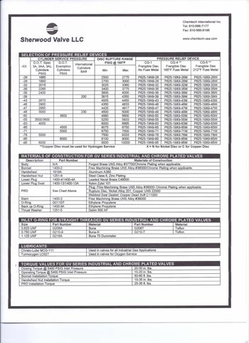
Pressure Relief Devices

Almost all compressed gas containers are fitted with pressure relief devices. A pressure relief device is a pressure- and/or temperature-activated device used to prevent the pressure from rising above a predetermined maximum, and thereby prevent rupture of a normally charged cylinder when subjected to a standard fire test as required by Title 49 of the U.S. Code of Federal Regulations (49CFR 173.34(d)), or equivalent regulations of Transport Canada.
The Compressed Gas Association, in pamphlet CGA S-1.1, has classified pressure relief devices according to type using the letter designation CG followed by a numeral. Each of these types described are in the following subsections (reference CGA S-1.1).
Type CG-1 (Pressure Relief Rupture Disk)
A rupture disk (synonymous with the name burst disk within the industry) is a pressure-operated device which affords protection against development of excessive pressure in cylinders. This device is designed to sense excess
pressure in a cylinder and will function when the cylinder is of sufficient magnitude to cause the rupture or bursting of the rupture disk element, thereby venting the contents of the cylinder. The rupturing of the rupture
disk element results in a non-reclosing orifice.
Rupture disk devices installed on compressed gas cylinders may be either an integral part of the cylinder valve assembly or may be installed on the cylinder as an independent attachment. The materials of construction selected must be compatible with the fluid in the cylinder as well as the cylinder valve materials with which the rupture disk device comes in contact in order to minimize corrosion.
One of the most common types of rupture disk devices consists of a gasket and a rupture disk and a rupture disk holder. These components are only supplied as factory-assembled devices designed to be replaced as a unit. The gasket is the part which provides the proper seal to prevent leakage of the cylinder contents past the rupture disk assembly and may be constructed of metallic or nonmetallic materials.
The rupture disk is the operating part of the pressure relief device and, when installed in a proper rupture disk holder, is designed to burst at a predetermined pressure to permit discharge of the cylinder contents. Such disks are usually made of metallic materials and may be of flat, preformed, reinforced, grooved or scored construction. Nonmetallic materials are also used for specific applications.
The rupture disk holder is the part of the pressure relief device which contains the opening, against which the rupture disk mates. The rupture disk holder usually also contains the discharge porting or passages, beyond the operating parts of the device, through which fluid must pass to reach the atmosphere. In many cases, the discharge holder is provided with radial vent holes through which the fluid in the cylinder vents to the atmosphere. This radical discharge design provides an anti-recoil feature, which minimizes rocketing of compressed gas cylinders during discharge of the contents through the pressure relief device. Other types of discharge ports may also be provided in rupture disk holders to suit specific application requirements.
Most rupture disk devices are designed with holders having either sharpedged or radius-edged orifices to which the rupture disk mates. The sharpedged orifice produces a shear-type actuation mode whereby the disk ruptures in shear, producing a characteristic leaf-type configuration after functioning.
The radius-edged orifice produces a tension-type actuation made whereby the disc stretches over the radius-edge. This thins the center of the disc until it can no longer hold the pressure. This type of rupture produces a characteristic rose petal configuration after functioning.
Since the actuation modes of each type of holder described above are completely different, it is important that only original manufacturer’s assemblies be used in the replacement of rupture disk devices.
WARNING The pressure relief rupture disk device is a primary safety component and hence the following precautions should be noted and adhered to:
A. Only trained personnel should be permitted to service pressure relief devices
B. Tightening of the rupture disk assembly to the cylinder valve or to the cylinder itself should be in accordance with the manufacturer’s instructions. Tightening to a torque less than the manufacturer’s recommendations may result in a leaking device or a device that may rupture at a lower pressure than specified. Conversely, over tightening can also result in disk actuation at a lower pressure than specified due to excessive twisting action, which may create wrinkles or distortions in the disk, which may cause premature failure of the disk and inadvertent release of the pressure contents. Either of these premature releases could cause serious injury or death.
WARNING Components of devices designed to rupture in shear are very similar in appearance to those designed to rupture in tension but are not interchangeable because they have completely different modes of actuation. If components are inadvertently interchanged, i.e. a disk designed to rupture in shear is installed in a rupture disk holder designed to rupture in tension, a serious cylinder failure incident could result that could lead to loss of life due to the significant increase in pressure required to rupture the disk. Conversely if a disk designed to rupture in tension is installed in a rupture disk holder designed to rupture in shear, premature rupture could occur with complete loss of contents due to significant reduction in rupture pressure of the disk. That may lead to fire, personal injury or death.
Limitations
A rupture disk is a pressure-operated device which affords protection against excessive pressure. It protects against excessive pressure when the properties of the gas, cylinder design, and percentage of charge in the cylinder are such that exposure to excessively high temperatures will cause an increase in internal pressure sufficient to actuate the rupture disk before the cylinder loses its integrity and weakens. The rupture disk also
protects against excessive pressure due to improper charging practices such as overfilling.
A rupture disk is a non-reclosing device. Once the disk has ruptured, there is no way to prevent the complete release of the contents of the cylinder. This device does not provide good protection against pressures caused by exposure to excessively high temperatures when the cylinder is only partially charged. The pressure rise may not be sufficient to actuate the rupture disk before the cylinder loses its integrity and weakens.
Consideration should be given to environmental conditions to which the cylinder may be exposed. Severely corrosive atmospheres may contribute to premature rupture of the disk. To prevent corrosion of the rupture disk, care must be taken to select materials of construction that do not interact with either the contents of the cylinder or the anticipated environmental conditions.
Type CG-2 and CG-3 (Fusible Plugs)
A fusible plug is a thermally operated pressure relief device which affords protection against excessive pressure developed by exposure to excessive heat. Once sufficient heat melts the fusible alloy, the entire contents of the cylinder will be vented. The CG-2 fusible alloy has a nominal melt temperature of 165˚ F (73.9˚ C); the CG-3 fusible metal has a nominal melt temperature of 212˚ F (100˚ C).
Fusible plugs can be installed on the cylinder as independent devices or fusible alloy can be cast directly into a suitable orifice in the cylinder valve body. In some cases, a fusible plug may be installed as a separate device
into the cylinder valve body.
WARNING No attempt should be made to repair fusible plug devices. They are not repairable and attempts to repair will destroy the integrity of the fusible alloy causing leakage of gases that may lead to fire, personal injury or death.
Limitations:
Since the fusible plus is a thermally operated device, it is designed to function only when the fusible metal melts out. Hence, it does not protect against over pressure from improper charging practices. Sufficient heat to melt the fusible alloy is necessary for proper functioning of this type of device. Therefore, the location of such devices is an important consideration.
Industry practice limits the application of these style fusible plugs to cylinders with 500 psig (3447 kPa) service pressure or less to minimize the possibility of cold flow or extrusion of the fusible alloy. A fusible device is a
nonreclosing devices and when it functions, it releases the entire contents of the cylinder.
Type CG-4 and CG-5 (Combination Rupture Disk/Fusible Plug)
A combination rupture disk/fusible plug pressure relief device requires both excessive pressure and excessive temperature to cause it to operate.
Sufficient heat is required to first melt out the fusible metal, after which the device will afford the same protection as the CG-1 rupture disk device. The CG-4 combination device has fusible alloy with a nominal melt
temperature of 165˚ F (73.9˚ C). The CG-5 combination device has fusible alloy with a nominal melt temperature of 212˚ F (100˚ C).
In this type of device, the rupture disk portion (CG-1) is directly exposed to the internal cylinder pressure, and so it is directly upstream of the fusible metal. In general, the same components that make up the CG-1 device are
used and the vent portion or downstream side of the rupture disk is thus reinforced against rupturing by the fusible alloy, and the fusible alloy is reinforce against extrusion by the rupture disk.
NOTE: The same precautions noted for CG-1 devices should be adhered to for CG-4 and CG-5 device. See previous warnings.
Limitations:
CG-4 and CG-5 combination devices function only in the presence of both excessive heat and excessive pressure, and sufficient heat must be present first to melt the fusible metal. Therefore, this device does not offer protection against over pressure from improper charging practices.
Type CG-7 (Pressure Relief Valves)
A pressure relief valve is a spring-loaded pressure-operated device designed to relieve excessive cylinder pressure, reclose, and reseal to prevent further release of product from the cylinder after excessive pressure is removed and valve resealing pressure has been achieved.
The primary advantage of using the pressure relief valve is that functioning of this type of device may not release all of the contents of the cylinder but is designed to reseal after resealing pressure has been achieved. This characteristic, in fire conditions, will minimize feeding the fire in the case of flammable or combustible cylinder contents.
Limitations:
Pressure relief valves are designed to maintain the pressure in the cylinder at a limit as determined by the spring force. Therefore, such devices do not protect the cylinder against possible rupture when continued application of external heat or direct flame impingement weakens the cylinder wall to the point where its rupture pressure is less than the operating pressure of the relief valve.
If you require assistance in selecting a Pressure Relief or Safety device for a specific application, please contact Sherwood Customer Service at 888-508-2583 with the following information: Part number of the valve assembly being repaired, if applicable; Type of gas service in which cylinder will be used; and service or test pressure of the cylinder.
Pressure Relief Device Numbering Matrix: Unitized Plug Series

Product Markings Reference


DOs and DO NOTs for Valve Use
Source: Compressed Gas Association, Inc. CGA V-9, 2012, p. 39
DOs
Proper care of compressed gas cylinder valves includes (but is not limited to) the following:
- Stored valves shall be packaged so cleanliness is maintained and adequate protection against damage during handling is provided.
- Valves should be visually inspected at each refill for any signs of damage or leakage.
- Question the supplier when a valve malfunctions and the problem cannot be diagnosed.
- Inspect PRDs per CGA S-1.1 before each refilling.
- Verify that a particular valve is suitable for both the cylinder and the commodity with which it is intended to be used.
- Open the valve slowly to prevent development of high pressure surges and heat generation on downstream equipment.
- When replacing PRDs, only original manufacturers’ assemblies and parts shall be used unless the interchange of parts is proven by suitable test.
- When replacing PRDs, refer to the marking on the device to ensure the proper rated device is installed.
- When the cylinder is not in use, even when empty, the valve should be in the closed position with the outlet cap in place and the transport cap installed.
- Check the condition of both the inlet and outlet threads before inserting a valve into a cylinder to ensure that the threads are not damaged, especially the first thread. A damaged first inlet thread could adversely affect
insertion. If the damage cannot be repaired by manually deburring with a file, replace the valve. - Handle valves carefully to avoid damage, especially to threads, which could prevent proper connection to mating parts.
- Replace the valve or PRD whenever any of its required markings are no longer legible.
- Valves that are shipped not fully assembled or with unattached components shall be protected from contamination.
- Only lubricants specially prepared for oxygen service shall be used on tapered threaded inlet connections.
NOTE: Not all PTFE tapes are suitable for oxygen service. Only PTFE tapes suitable for oxygen service shall be used.
DO NOTs
This list is not intended to be comprehensive. The user is cautioned to review maintenance activity with the valve supplier before beginning work if there is any uncertainty on the part of the user. Proper care of compressed gas valves includes the following:
- Do not use a damaged valve where function or integrity might have been affected.
- Do not continue to use a valve that operates abnormally, such as it becoming noisy or progressively harder to operate.
- Do not try to recondition a valve until the design and operations of the valve are fully understood and the proper tools are available.
- Do not reuse a valve having a tapered inlet thread with less than four full threads showing after it is installed into the cylinder hand-tight.
- Do not use an automatic operator, adapter, wrench or other tool to obtain a greater mechanical advantage on handwheel-operated valves without first consulting with the valve manufacturer to ensure that the applied torque does not exceed the safe operating torque for the valve.
- Do not use the number of exposed valve threads to determine whether a valve is adequately engaged and leak tight in a cylinder. (See CGA V-11, General Guidelines for the Installation of Valves into High Pressure Aluminum Cylinders, for valve installed in aluminum cylinders.) Even with a new valve in a new steel cylinder, both with nominal ¾”–14 NGT threads, the number of exposed full threads after three wrenched turns can vary between two and five.
- Do not lubricate valve internal surfaces with the pressure boundary without first checking with the valve manufacturer.
- Do not lubricate oxygen service valve threads (to cylinder threads) for installation in straight-threaded aluminum.
- Do not use poor fitting jaws on valving machines because they could cause:
– Excessive bending and torsional forces into the valve
– Rounding off of valve wrench flat corners with obliteration of valve identification
markings, or
– Interference of jaws with valve outlet, PRD, etc., resulting in damage and leaks - Do not lift, drag or move a cylinder using the valve handwheel as a handle. It is not designed for this purpose and doing so can cause the valve to open.
- Do not use adapters to adapt the CGA valve outlet connection to another CGA valve outlet connection unless adapters satisfy the conditions for their use specified in CGA V-1.
- Do not put a reconditioned valve into service unless it has been tested to this standard.
- Do not use internal operating replacement parts unless they were supplied by the valve manufacturer.
Valve Part Numbering Matrix: Global Valves

Get a Custom Quote
Fill out the form below.

Gas Cylinder Valve Catalogs

Watch Our Videos
Copyright © 2017 Chemtech International, INC. All Rights Reserved | Privacy Policy | Terms & Conditions
Copyright © 2017 Chemtech International, INC. All Rights Reserved
Privacy Policy
Terms & Conditions